
- Posts: 5
- Thank you received: 0
Log In

Log in

Ignition monitoring system
4 years 2 months ago #22199
by Arneil
Ignition monitoring system was created by Arneil
I am having driveability problems with my S4 involving the ignition monitoring system. My question is how can the system work as described when the temperature sensors are in series? Or more to the point how can the system determine from the temperature sensors which ignition system isn't working when each fires two cylinders on each bank? When an ignition system fails both sides of the engine are going to experience the same cooling off.
Please Log in or Create an account to join the conversation.


4 years 2 months ago #22213
by Rich928
Rich
Membership Chairman
Charter Member
1993 928 GTS Cover Girl
1987 928 S4
1979 928 5-speed rescue
1979 928 5-liter track beast
Replied by Rich928 on topic Ignition monitoring system
The 928 S4 and newer engines have two separate ignition circuits. Ignition circuit 1 is comprised of cylinders 1,4,6,7, the right side coil and distributor. Ignition circuit 2 is comprised of cylinders 2,3,5,8, the left side coil and distributor. If there is a failure in one of the ignition circuits, raw fuel is pumped out of the cylinders and into the exhaust system. When the raw fuel hits the hot catalytic converters a fire may occur – OUCH!
From model year 1989 onwards, Porsche added the Ignition Circuit Monitoring Relay as a safety feature. This circuit is completely independent of the LH injection system. It is identified in the workshop manual wiring diagram as the Ignition Control Circuit. The function of the system is to turn off the fuel injection to the failing ignition circuit. The inputs to the relay are two exhaust temperature sensors that provide input to the relay. If one of the ignition circuits fails, the “Ignition Circuit Monitoring Relay” shuts off the pulse signal to all of the fuel injectors of the affected circuit.As you might imagine, the symptoms of a shut down ignition circuit are a significant reduction in power and a rough running engine. For trouble shooting, you need to determine if the shut-down is due to a failed ignition circuit or a failure of the Ignition Circuit Monitoring Relay itself.The first step is to quickly identify which circuit is affected. Look at the clear relay module that is fitted next to the EZK spark control unit in the passenger compartment. When ignition circuit 1 (cylinders 1,4,6,7) is shut-down, a red LED is illuminated. When ignition circuit 2 (cylinders 2,3,5, is shut-down, a green LED is illuminated.Check the ignition circuits and repair as necessary. If no problem is found with the ignition circuit, there may be a failure of the Ignition Circuit Monitoring Relay circuit, the signals to test are:
Subject: Diagnosing Ignition Monitoring System (Porsche Tech Doc)
ATTENTION: Service Manager/Service Technician
Models Affected: 928 S4/GT/GTS From 1989 Models –
Concern: Checking of components after activation of the ignition monitoring system (injection circuit switched off fault codes 1131 of 1231). Activation may be caused by the following:
- Damaged or defective exhaust gas temperature sensors.
- Possible damage to the ignition coil wire left side (in driving direction) between the ignition coil and distributor cap.
- Poor grounding of the mounting plate for the ignition final stages.
- Poor physical connection of the electrical plugs on the ignition final stages.
Parts Information:
New version temperature sensor Part Number 928 606 155 02 New coil wire with
hose covering Part Number 928 602 040 01 (for left side)
Repair Information: 1. Check the left side ignition coil wire. Be certain the coil wire is routed freely and not under tension. If damaged, replace with new version (see parts information).
2. Check all ignition components and connectors for corrosion, tightness, correct connection and damage. Repair or replace as necessary. If an ignition circuit has malfunctioned, an LED indication will be given by the ignition monitor relay located on the L-H control unit mounting plate.
Ignition circuit I (cyl. 1-7-6-4) Red diode
Ignition circuit II (cyl. 3-2-5- Green diode
3. Before replacing temperature sensors, check the voltage difference of both temperature sensors as per step 4 of this bulletin. Sensors are located in the exhaust ports:
Model '89-'90, cyl. 4 and 8
Model '91 cyl. 3 and 7
The function of the ignition circuits and light diodes located in the ignition monitor relay remains unchanged. It is not possible to determine from the LED display of the ignition monitor relay if one or both temperature sensors are defective or which temperature sensor has failed. When installing temperature sensors, coat the sensor adapter threads with molykote paste HTP (white) and torque sensors to 10 N-m.
4. The voltage difference of the temperature sensors must be checked in order to ensure proper operation of the ignition monitor system.
Checking sensor voltage difference:
- Start engine and bring to operating temperature.
- Loosen the mounting bolt for the ignition monitor relay and pivot the relay up to gain access to the plug terminals Do not disconnect the relay plug.
- Set volt meter to the millivolt range and connect leads between E1 and E2 of ignition monitor relay (Figure 3, white wires). A digital volt meter must be used. Polarity is not important.
- Measure voltage with the engine idling and again at approximately 2000 RPM. A maximum difference of +2.5 mV or -2.5 mV (depending on polarity) is permitted. If the voltage difference is above 2.5 mV, stop the engine, loosen and rotate one temperature sensor. Retighten sensor and check voltage difference. If the difference is above 2.5 mV, stop the engine and rotate the other sensor. If after rotating the sensors to different positions, the voltage difference is too high (above 2.5 mV) the temperature sensors are
defective and must be replaced.
How to “jumper” around the Ignition monitor:
Look at the 9 pin connector, there's a fat red wire feeding 12V power to the center slot. Then there are two 'output' wires to the sensors, E1 and E2. They have a red/yellow stripe and a red/green stripe. So to jumper things you just need a 'Y'/three way jumper that sends power from the center to both pins.
From model year 1989 onwards, Porsche added the Ignition Circuit Monitoring Relay as a safety feature. This circuit is completely independent of the LH injection system. It is identified in the workshop manual wiring diagram as the Ignition Control Circuit. The function of the system is to turn off the fuel injection to the failing ignition circuit. The inputs to the relay are two exhaust temperature sensors that provide input to the relay. If one of the ignition circuits fails, the “Ignition Circuit Monitoring Relay” shuts off the pulse signal to all of the fuel injectors of the affected circuit.As you might imagine, the symptoms of a shut down ignition circuit are a significant reduction in power and a rough running engine. For trouble shooting, you need to determine if the shut-down is due to a failed ignition circuit or a failure of the Ignition Circuit Monitoring Relay itself.The first step is to quickly identify which circuit is affected. Look at the clear relay module that is fitted next to the EZK spark control unit in the passenger compartment. When ignition circuit 1 (cylinders 1,4,6,7) is shut-down, a red LED is illuminated. When ignition circuit 2 (cylinders 2,3,5,
is shut-down, a green LED is illuminated.Check the ignition circuits and repair as necessary. If no problem is found with the ignition circuit, there may be a failure of the Ignition Circuit Monitoring Relay circuit, the signals to test are:
- Terminal 31: ground
- Ground must be present at terminal AL when the ignition switch is in the off position.
- Battery voltage must be present at terminals A1, A2, 15 and 87 when the ignition is in the on position.
- Battery voltage must be present at terminals AL and 61 when the engine is running.
- A Voltage value of approximately 2.7 V must be present at both terminals E1 and E2 when the ignition is in the on position.
- The resistance between E1 and E2 is approximately 5 – 10 Ohms (measured at the disconnected relay socket).
Subject: Diagnosing Ignition Monitoring System (Porsche Tech Doc)
ATTENTION: Service Manager/Service Technician
Models Affected: 928 S4/GT/GTS From 1989 Models –
Concern: Checking of components after activation of the ignition monitoring system (injection circuit switched off fault codes 1131 of 1231). Activation may be caused by the following:
- Damaged or defective exhaust gas temperature sensors.
- Possible damage to the ignition coil wire left side (in driving direction) between the ignition coil and distributor cap.
- Poor grounding of the mounting plate for the ignition final stages.
- Poor physical connection of the electrical plugs on the ignition final stages.
Parts Information:
New version temperature sensor Part Number 928 606 155 02 New coil wire with
hose covering Part Number 928 602 040 01 (for left side)
Repair Information: 1. Check the left side ignition coil wire. Be certain the coil wire is routed freely and not under tension. If damaged, replace with new version (see parts information).
2. Check all ignition components and connectors for corrosion, tightness, correct connection and damage. Repair or replace as necessary. If an ignition circuit has malfunctioned, an LED indication will be given by the ignition monitor relay located on the L-H control unit mounting plate.
Ignition circuit I (cyl. 1-7-6-4) Red diode
Ignition circuit II (cyl. 3-2-5-
Green diode3. Before replacing temperature sensors, check the voltage difference of both temperature sensors as per step 4 of this bulletin. Sensors are located in the exhaust ports:
Model '89-'90, cyl. 4 and 8
Model '91 cyl. 3 and 7
The function of the ignition circuits and light diodes located in the ignition monitor relay remains unchanged. It is not possible to determine from the LED display of the ignition monitor relay if one or both temperature sensors are defective or which temperature sensor has failed. When installing temperature sensors, coat the sensor adapter threads with molykote paste HTP (white) and torque sensors to 10 N-m.
4. The voltage difference of the temperature sensors must be checked in order to ensure proper operation of the ignition monitor system.
Checking sensor voltage difference:
- Start engine and bring to operating temperature.
- Loosen the mounting bolt for the ignition monitor relay and pivot the relay up to gain access to the plug terminals Do not disconnect the relay plug.
- Set volt meter to the millivolt range and connect leads between E1 and E2 of ignition monitor relay (Figure 3, white wires). A digital volt meter must be used. Polarity is not important.
- Measure voltage with the engine idling and again at approximately 2000 RPM. A maximum difference of +2.5 mV or -2.5 mV (depending on polarity) is permitted. If the voltage difference is above 2.5 mV, stop the engine, loosen and rotate one temperature sensor. Retighten sensor and check voltage difference. If the difference is above 2.5 mV, stop the engine and rotate the other sensor. If after rotating the sensors to different positions, the voltage difference is too high (above 2.5 mV) the temperature sensors are
defective and must be replaced.
How to “jumper” around the Ignition monitor:
Look at the 9 pin connector, there's a fat red wire feeding 12V power to the center slot. Then there are two 'output' wires to the sensors, E1 and E2. They have a red/yellow stripe and a red/green stripe. So to jumper things you just need a 'Y'/three way jumper that sends power from the center to both pins.
Rich
Membership Chairman
Charter Member
1993 928 GTS Cover Girl
1987 928 S4
1979 928 5-speed rescue
1979 928 5-liter track beast
Please Log in or Create an account to join the conversation.
4 years 2 months ago #22219
by Arneil
Replied by Arneil on topic Ignition monitoring system
I really appreciate the extensive info provided by Rich! But I still don't understand how the system can determine which ignition module is not working when they each fire two cylinders on both banks. To quote the old joke about the Thermos bottle keeping hot things hot and cold things cold, HOW DO IT KNOW?
Please Log in or Create an account to join the conversation.
4 years 2 months ago #22224
by Rich928
Rich
Membership Chairman
Charter Member
1993 928 GTS Cover Girl
1987 928 S4
1979 928 5-speed rescue
1979 928 5-liter track beast
Replied by Rich928 on topic Ignition monitoring system
Think of it this way, the Porsche 928 ignition system really is implemented as two separate 4-cylinder engines connected by a common crank shaft but is controlled by a single digital control module (Bosch EZF or EZK depending upon model year). The separate engines are cylinders 1,4,6,7 and cylinders 2,3,5,8. There are two coils and two distributors as part of this two “engine” solution. So if one of the two systems fails for any reason those four cylinders have no spark and the injected air/fuel mixture is just pushed out the exhaust into the hot catalytic converter where it ignites and burns. If the engine wasn’t promptly shut down when one of the two spark systems failed, a car fire could happen. So if you own a 1984 Euro, or 1985 - 1988 Porsche 928 if engine the power quickly decreases by 50% PLEASE pull over and turn off the engine otherwise a car fire can occur! To solve this problem which had been lurking since the advent of the dual spark system initiated with the 1984 Euro 16 valve motors & 32 valve 1985 engines Porsche created the “The Ignition Circuit Monitoring Relay” that utilizes exhaust gas temperature sensors to determine if there is a difference in the temperature between the “two engine” exhaust streams. All that is necessary is to measure the temperature from one cylinder of each of the two systems. This monitoring system turns off the fuel injectors to the cylinder set that has the cooler exhaust stream” thus stopping the flow of uncombusted air/fuel mixture into the hot catalytic converter.
Rich
Membership Chairman
Charter Member
1993 928 GTS Cover Girl
1987 928 S4
1979 928 5-speed rescue
1979 928 5-liter track beast
Please Log in or Create an account to join the conversation.
4 years 1 month ago #22228
by Arneil
Replied by Arneil on topic Ignition monitoring system
Rich, you know I have the highest regard for your knowledge and experience but I feel like I'm not speaking English. Your troubleshooting advise strongly hints at one of my objections that the system can't work as described. You instruct someone trying to diagnose the system to turn one temperature sensor and then the other to determine which one may be responsible for an abnormal voltage reading. That's my first question, how can identical electronic components in series detect which is active or malfunctioning? Identifying the ignition systems as left and right only is useful because they are physically located there, each one fires TWO CYLINDERS ON EACH BANK, so how can temperature sensors tell which one is faulty? If you can find the time to reply again PLEASE address these questions!
Please Log in or Create an account to join the conversation.
4 years 1 month ago #22229
by Rich928
Rich
Membership Chairman
Charter Member
1993 928 GTS Cover Girl
1987 928 S4
1979 928 5-speed rescue
1979 928 5-liter track beast
Replied by Rich928 on topic Ignition monitoring system
Question: How can identical electronic components in series detect which is active or malfunctioning? Identifying the ignition systems as left and right only is useful because they are physically located there, each one fires TWO CYLINDERS ON EACH BANK, so how can temperature sensors tell which one is faulty? If you can find the time to reply again PLEASE address these questions!
Answer: Information from the Porsche Service Info Tech 1989 manual is a great source!
Thermo Element
Two wires made of different metals (nickle-chrome and nickle) are welded together on one end. If the point of connection is heated, electric voltage (thermo voltage) is produced. The amount of voltage depends on the thermically effective wire length (I), the materials of wires and the applied temperature.
Basically it concerns very low voltage, which is in a range of 4 mV for each 100C difference in temperature.
Schematic of connection
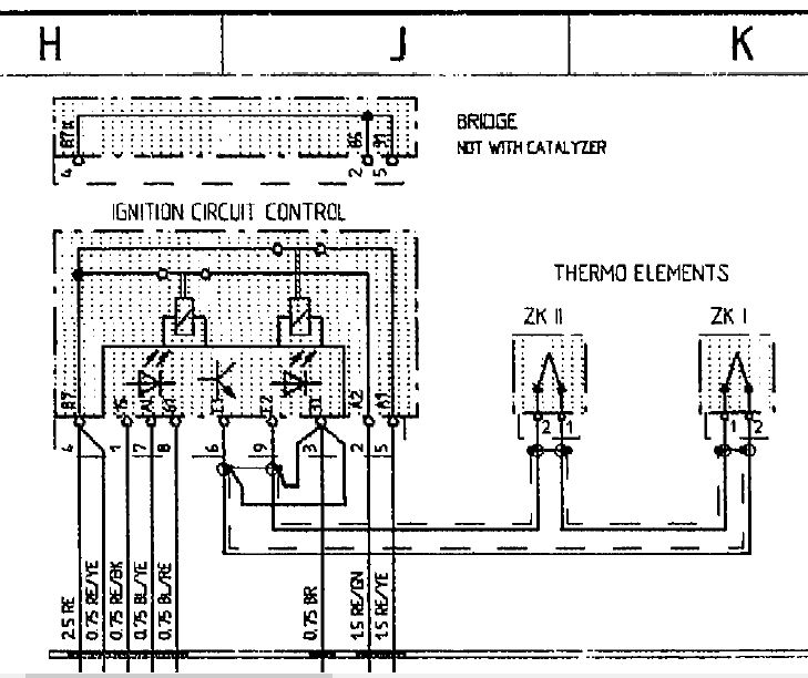
Look to the schematic, the Thermo Elements ZKI and ZKII have termials 1 and 2. The wiring is that the terminal 2 is the shielded signal input:
ZKI terminal 2 connects to Ignition Control circuit pin 6
ZKII Terminal 2 connects to Ignition Control circuit Pin 9
Description
One each thermo element is screwed in exhaust ports of cylinders 4 and 8, where secondary air injection is connected in cars without a catalytic converter. These
thermo elements monitor the exhaust temperature of cylinders 4 and 8.
Division of Ignition Circuits:
Ignition Circuit I: 1 7 6 4
Ignition Circuit II: 3 2 5 8
If an ignition circuit (e.g. ignition circuit I) would now fail, there would no longer be combustion in cylinder 4 and the exhaust temperature would drop. This drop in exhaust temperature is registered by the thermo element and sent as an electric signal to an ignition circuit monitoring relay. This relay recognizes the temperature difference (as voltage difference) and switches off the corresponding injection circuit for the failed ignition circuit.
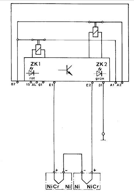
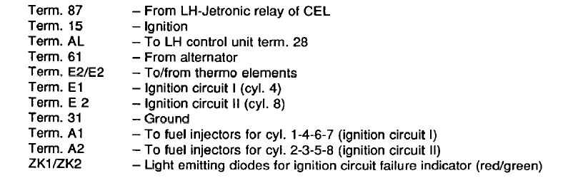
Description
Terminals El and E2 of the ignition circuit monitoring relay will each have the same voltage after starting the engine and heating-up of thermo elements (with perfect condition ignition circuits).
If one ignition circuit would fail and the exhaust temperature drops, there would be less voltage on the pertinent terminal (El or E2), depending on which ignition circuit has failed. This difference in voltage will be recognized by the ignition circuit monitoring relay.
A relay contact in the relay belonging to the failed ignition circuit is opened and interrupts the supply of power to the fuel injectors of this ignition circuit. One of two colored light emitting diodes in the relay lights up at the same time.
It is easy to recognize which ignition or injection circuit is concerned when an injection circuit is
switched off because of the different colored light emitting diodes and transparent relay housing.
Red LED: Ignition Circuit I
Green LED: Ignition Circuit II
The relay switches off fuel injection as from a voltage difference of 6 mV, which is equal to a difference in temperature of about 150C.
Special Features of lgnltion Circuit Monltorlng Relay
Since the four cylinders still draw in air after switching off the injection circuit, the oxygen sensor would recognize excessive air and regulate the air/fuel mixture of the perfect condition cylinders in rich direction. Oxygen sensor control is switched off together with switching off the ignition circuit, in order to prevent this.
Terminal 15 of the relay has voltage via CEL when turning on the ignition.
Terminal AL of the relay (this wire leads to LH control unit term. 28) has ground with “ignition on”. With “ignition on” the LH control unit will be coded for operation without catalytic converter via term. AL of the relay, since the coding, whether with or without catalytic converter, for the LH control unit is accomplished via positive or ground on term. 28 of the LH control unit. If the engine is started and term. 61 of the relay has alternator voltage, voltage is supplied to term. AL and the LH control unit is therefore coded for operation “with catalytic converter”. If an ignition circuit would now fail and the pertinent relay contact opens. ground would be applied on term. AL and the LH control unit switches over to operation “without catalytic converter”.
Since, however, in cars without catalytic converter idle speed CO level adjustments are made via a potentiometer and this potentiometer on the other hand is not installed in cars with catalytic converter (adaptive oxygen sensor control), a 150 ohm resistor integrated in the coding plug of the LH or EZK control unit sends a fixed value (replacement value) to the LH control unit for guarantee of engine idling when the ignition circuit monitoring relay switches and therefore oxygen sensor control is switched over to control without oxygen sensor.
Answer: Information from the Porsche Service Info Tech 1989 manual is a great source!
Thermo Element
Two wires made of different metals (nickle-chrome and nickle) are welded together on one end. If the point of connection is heated, electric voltage (thermo voltage) is produced. The amount of voltage depends on the thermically effective wire length (I), the materials of wires and the applied temperature.
Basically it concerns very low voltage, which is in a range of 4 mV for each 100C difference in temperature.
Schematic of connection
Look to the schematic, the Thermo Elements ZKI and ZKII have termials 1 and 2. The wiring is that the terminal 2 is the shielded signal input:
ZKI terminal 2 connects to Ignition Control circuit pin 6
ZKII Terminal 2 connects to Ignition Control circuit Pin 9
Description
One each thermo element is screwed in exhaust ports of cylinders 4 and 8, where secondary air injection is connected in cars without a catalytic converter. These
thermo elements monitor the exhaust temperature of cylinders 4 and 8.
Division of Ignition Circuits:
Ignition Circuit I: 1 7 6 4
Ignition Circuit II: 3 2 5 8
If an ignition circuit (e.g. ignition circuit I) would now fail, there would no longer be combustion in cylinder 4 and the exhaust temperature would drop. This drop in exhaust temperature is registered by the thermo element and sent as an electric signal to an ignition circuit monitoring relay. This relay recognizes the temperature difference (as voltage difference) and switches off the corresponding injection circuit for the failed ignition circuit.
Description
Terminals El and E2 of the ignition circuit monitoring relay will each have the same voltage after starting the engine and heating-up of thermo elements (with perfect condition ignition circuits).
If one ignition circuit would fail and the exhaust temperature drops, there would be less voltage on the pertinent terminal (El or E2), depending on which ignition circuit has failed. This difference in voltage will be recognized by the ignition circuit monitoring relay.
A relay contact in the relay belonging to the failed ignition circuit is opened and interrupts the supply of power to the fuel injectors of this ignition circuit. One of two colored light emitting diodes in the relay lights up at the same time.
It is easy to recognize which ignition or injection circuit is concerned when an injection circuit is
switched off because of the different colored light emitting diodes and transparent relay housing.
Red LED: Ignition Circuit I
Green LED: Ignition Circuit II
The relay switches off fuel injection as from a voltage difference of 6 mV, which is equal to a difference in temperature of about 150C.
Special Features of lgnltion Circuit Monltorlng Relay
Since the four cylinders still draw in air after switching off the injection circuit, the oxygen sensor would recognize excessive air and regulate the air/fuel mixture of the perfect condition cylinders in rich direction. Oxygen sensor control is switched off together with switching off the ignition circuit, in order to prevent this.
Terminal 15 of the relay has voltage via CEL when turning on the ignition.
Terminal AL of the relay (this wire leads to LH control unit term. 28) has ground with “ignition on”. With “ignition on” the LH control unit will be coded for operation without catalytic converter via term. AL of the relay, since the coding, whether with or without catalytic converter, for the LH control unit is accomplished via positive or ground on term. 28 of the LH control unit. If the engine is started and term. 61 of the relay has alternator voltage, voltage is supplied to term. AL and the LH control unit is therefore coded for operation “with catalytic converter”. If an ignition circuit would now fail and the pertinent relay contact opens. ground would be applied on term. AL and the LH control unit switches over to operation “without catalytic converter”.
Since, however, in cars without catalytic converter idle speed CO level adjustments are made via a potentiometer and this potentiometer on the other hand is not installed in cars with catalytic converter (adaptive oxygen sensor control), a 150 ohm resistor integrated in the coding plug of the LH or EZK control unit sends a fixed value (replacement value) to the LH control unit for guarantee of engine idling when the ignition circuit monitoring relay switches and therefore oxygen sensor control is switched over to control without oxygen sensor.
Rich
Membership Chairman
Charter Member
1993 928 GTS Cover Girl
1987 928 S4
1979 928 5-speed rescue
1979 928 5-liter track beast
Please Log in or Create an account to join the conversation.